I first gathered all the necessary components: the analog controls, input/output jacks, resistors, capacitors, transistors, and of course the enclosure.

I connected most components onto a perfboard base, which basically functions as a lighter-weight breadboard. Since I haven’t really worked with transistors or tried to solder up a circuit this complicated before, it took a bit of time to make sure I connected everything correctly and as neatly as possible.
On the metal enclosure, I drilled holes for the knobs, I/O jacks, LED enclosure, and push button.

With the components put it, just to see how it looked:

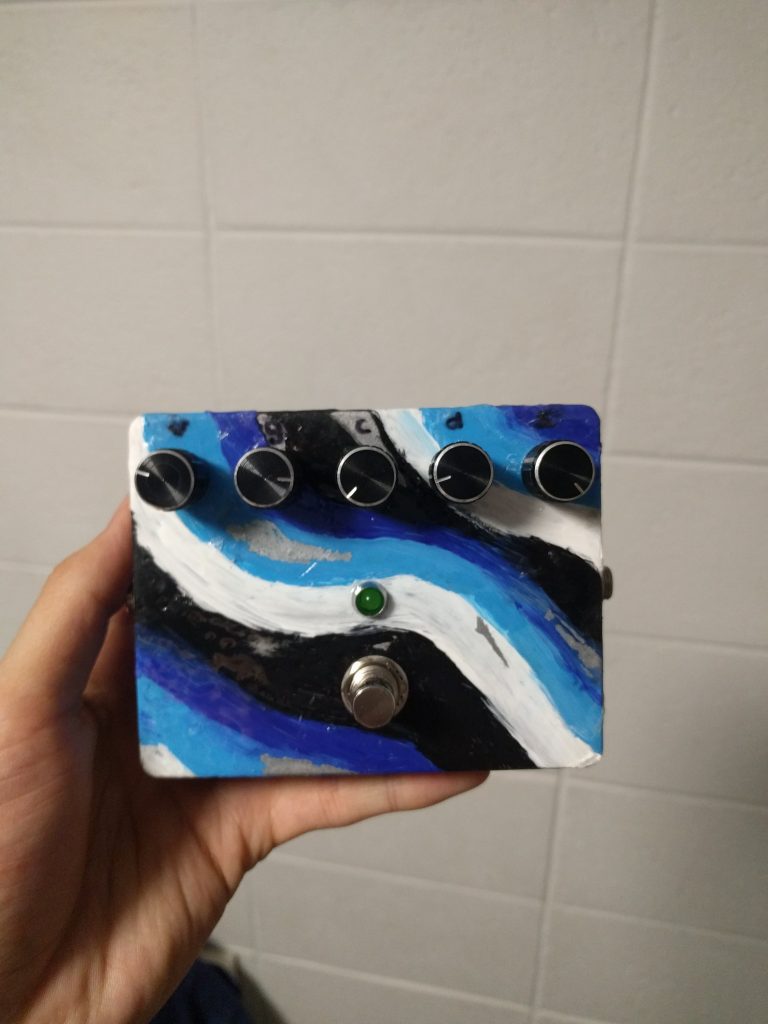
After I drilled the holes, I painted a simple design with acrylics and went over it with multiple layers of gloss finish. After that finished, I added the components back in.
Meanwhile, I soldered in the basic circuit. I used transistor holders (the circular parts with three holes) as opposed to directly soldering in the transistors, since soldering can damage transistors if you aren’t quick with it (and I knew from the get-go that I wouldn’t be that quick!).

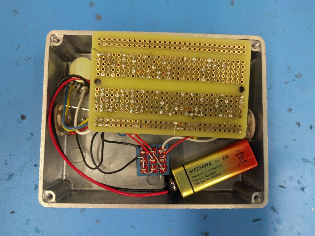
Once the circuit was fully connected, it was a (relatively) simple matter of screwing in all the components into the enclosure and soldering them together. Here are views with both the top and bottom of the perfboard exposed:
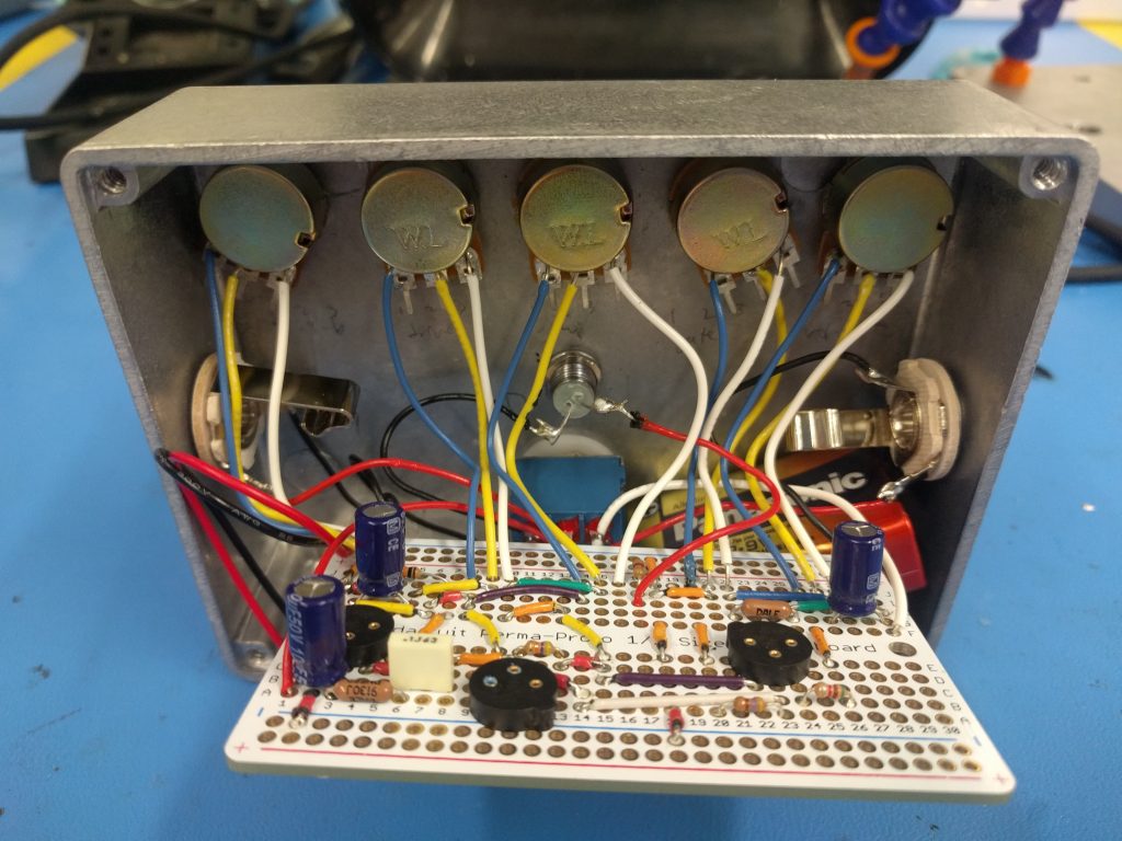
I had to learn the orientations of transistors, make sure the LED and electrolytic capacitors were in the correct directions, and figure out how to connect the DPDT switch. I ended up following this orientation:
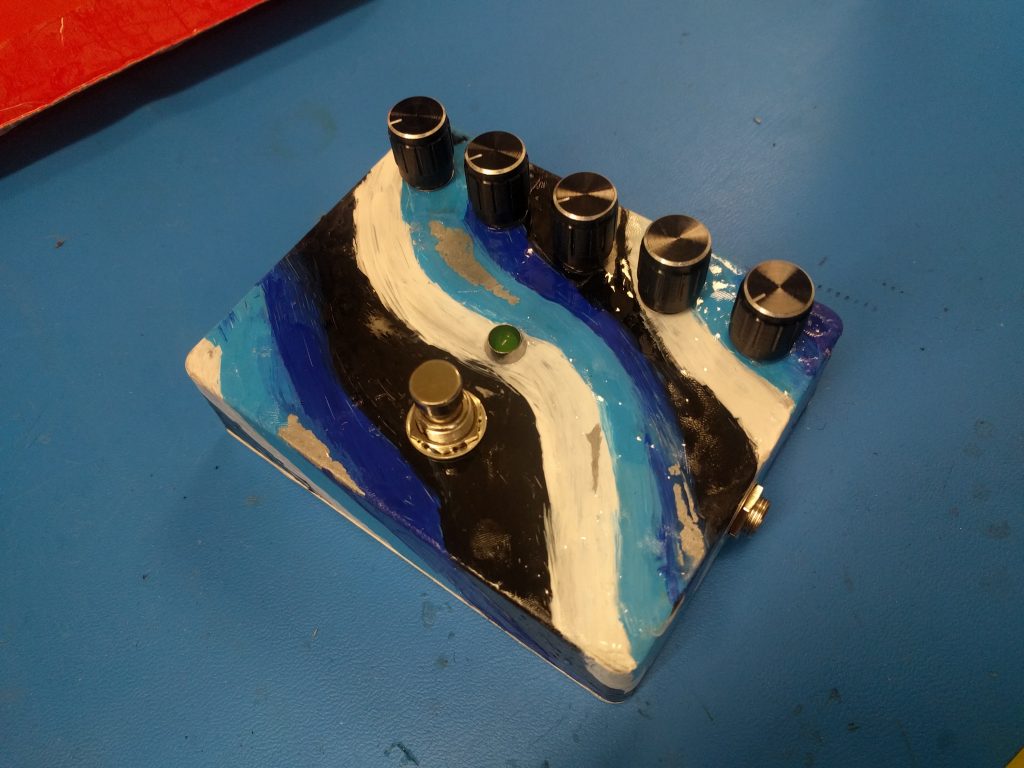
After all that building, my finished pedal:


 er
er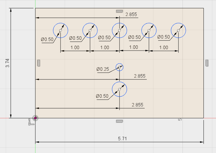
Recent Comments