You are viewing a read-only archive of the Blogs.Harvard network. Learn more.

Making My Own Fuzz Factory

Building a Guitar Pedal

Reflections and Analysis

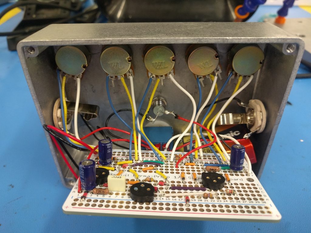
I encountered a lot of new topics as part of researching and building my guitar pedal. Even if the schematic is still tough to fully grasp, with all its feedback loops and sort of admittedly unpredictable control, I at least have a handle on what certain components can do. For example, I’d never worked with a DPDT switch before, but it is very useful in a guitar pedal: when the pedal is off, you need to have a clean signal go from input to output; when it is on, then your full circuit should kick in.

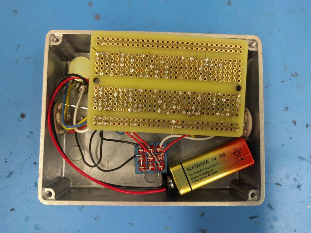
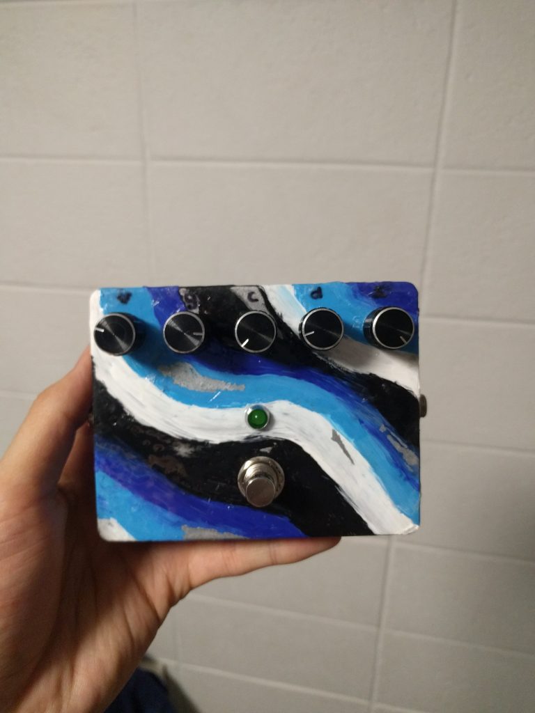
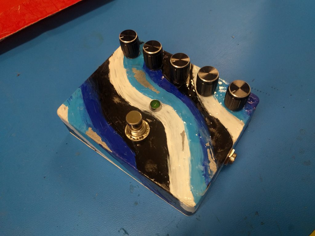
I also dealt with the headache of making sure nothing is shorting out, otherwise I didn’t get any output sound. Trying to fit all the components and soldering things cleanly was more difficult than I initially expected, so I could probably improve it by shortening certain wires (i.e. to the potentiometers, which currently have to bend to fully fit inside the enclosure). This is potentially also why my pedal has sporadic output issues if I force the perfboard too hard into the box — it’s something I will definitely look into in the future, since I’ve actually created my one and only guitar pedal, and it sounds pretty good when it works! 🙂

This project deals with some of the signal processing and transistor discussions we had in class, albeit on a much more complex and technical level. For example, I understand how a compressor is supposed to work, but it took me a bit to get its place within the full schematic. When it comes to full schematics like those for guitar pedals, it makes sense that they are quite complex compared to the concepts we touched on in lecture. I’m very happy with how my pedal turned out, even with its quirks, and that I was able to implement one of those (relatively) crazy circuit diagrams!


Testing

I had recently finished soldering everything and preparing the enclosure. To test it, I plugged in my electric guitar and amp. The bypass / clean sound works perfectly — but turning it on didn’t give me any sound anymore. The LED turned on, but even adjusting each of the knobs didn’t result in any sound.

I went back and thought about what might be causing it — and realized that when i soldered wires to the potentiometers, I let them poke up until the box. Well, the box itself is metal… so that must’ve been shorting things! So I loosened the pots and plugged in my guitar:

I’ll snipped off the excess, added electrical tape to hopefully prevent further shorts with the box, and tightened everything up. I’m still getting an issue if I tighten the bottom of the box all the way in, but if I give it a little slack, the pedal seems to work brilliantly!

Build Process

I first gathered all the necessary components: the analog controls, input/output jacks, resistors, capacitors, transistors, and of course the enclosure.

I connected most components onto a perfboard base, which basically functions as a lighter-weight breadboard. Since I haven’t really worked with transistors or tried to solder up a circuit this complicated before, it took a bit of time to make sure I connected everything correctly and as neatly as possible.

On the metal enclosure, I drilled holes for the knobs, I/O jacks, LED enclosure, and push button.

With the components put it, just to see how it looked:

After I drilled the holes, I painted a simple design with acrylics and went over it with multiple layers of gloss finish. After that finished, I added the components back in.

Meanwhile, I soldered in the basic circuit. I used transistor holders (the circular parts with three holes) as opposed to directly soldering in the transistors, since soldering can damage transistors if you aren’t quick with it (and I knew from the get-go that I wouldn’t be that quick!).

Once the circuit was fully connected, it was a (relatively) simple matter of screwing in all the components into the enclosure and soldering them together. Here are views with both the top and bottom of the perfboard exposed:

I had to learn the orientations of transistors, make sure the LED and electrolytic capacitors were in the correct directions, and figure out how to connect the DPDT switch. I ended up following this orientation:

After all that building, my finished pedal:


Design

The circuit schematic will be as shown in the image (or here http://basicaudio.net/Fuzz%20factory%20schem.PNG):

Another more graphical representation:

I wired up the configuration + the smaller components on a prototyping board / perfboard which will lie within the pedal enclosure, along with a 9V battery.

Even though the schematic is relatively simple for a guitar pedal, it was still a bit complicated for me, especially with all the feedback loops! To make sure I got the circuit correct, I printed out a version of the perfboard I used and drew in the circuit manually with pencil.

er

For the enclosure, I would like to use a metal enclosure for durability. Since the device uses electrical sound as both input and output, the enclosure material will not affect the actual signal processing. I’m thinking about using a Hammond enclosure (https://www.mammothelectronics.com/collections/hammond-enclosures).

The dimensions of the ZVex Fuzz Factory are 4.70″ x 2.38″ x 1.82″, so I’m thinking of giving myself some leeway by getting an enclosure that is 5.71″ x 3.74″ x 1.93″ (there wasn’t really a better enclosure size given the dimensions of the commercial pedal).

I’ll also plan on decorating the enclosure to some degree. I found this link: https://www.coda-effects.com/2017/10/enclosure-art-how-to-make-good-looking.html, which goes through a few methods of decorating pedals. I will need to decide which method I think looks best while being feasible. (Obviously, some of the more impressive designs and decorations are pretty expensive or inaccessible for DIY.)

As far as how the pieces will be mounted on the enclosure, on the top, there will be five potentiometers / knobs, a push button for power, and an LED to indicate ON/OFF. There will be input and output 1/4″ jacks.

Here is a simple CAD schematic I made; knobs on the top, push button on the bottom, LED in the middle:

Introduction

Description

I will be making my own guitar pedal based on the Zvex Fuzz Factory (https://www.zvex.com/products/fuzz-factory).  The Fuzz Factory is a fuzzbox, which is used to make a distorted, fuzzy effect to the signal from an electric guitar. The pedal provides a type of distortion by clipping the clean signal, adding various overtones and sustain.

Motivation

I play guitar in my spare time and record my own music. However, I’ve never actually purchased actual guitar pedal hardware, so I thought it would be fun and practical to build my own! In addition, along the way I’ll learn what’s going on under the hood in pedals that make a “fuzzy” effect. It definitely helps that the Fuzz Factory schematic is readily available online and seems to be the perfect scope for a final project.

Background Research

I found a sample schematic of the Fuzz Factory:

Another representation that’s a bit more pictorial:

According the Zvex, the manufacturer of the Fuzz Factory: “Although the five knobs are named for the parameters over which they seem to have the most control, please don’t hold me to it.”

  • Volume: output level
  • Gate: sets a floor for output sound
  • Compression: reduces loud sounds and amplifies low sounds
  • Drive: increases distortion
  • Stability: changes supply voltage

The pedal is popular with rock musicians; see Plug In Baby by Muse: https://www.youtube.com/watch?v=dbB-mICjkQM.

With these as guidelines, I will construct / solder up the circuit and place it within an enclosure, just like a commercial pedal!